

Atomic Skull
Well-known member
- Messages
- 788
- Reaction score
- 752
- Points
- 248
I do NOT recommend doing this getting those isolation grommets back in for reassembly was 30 minutes of struggle with tweezers and a magnifying visor.
MCU is a CKS32F
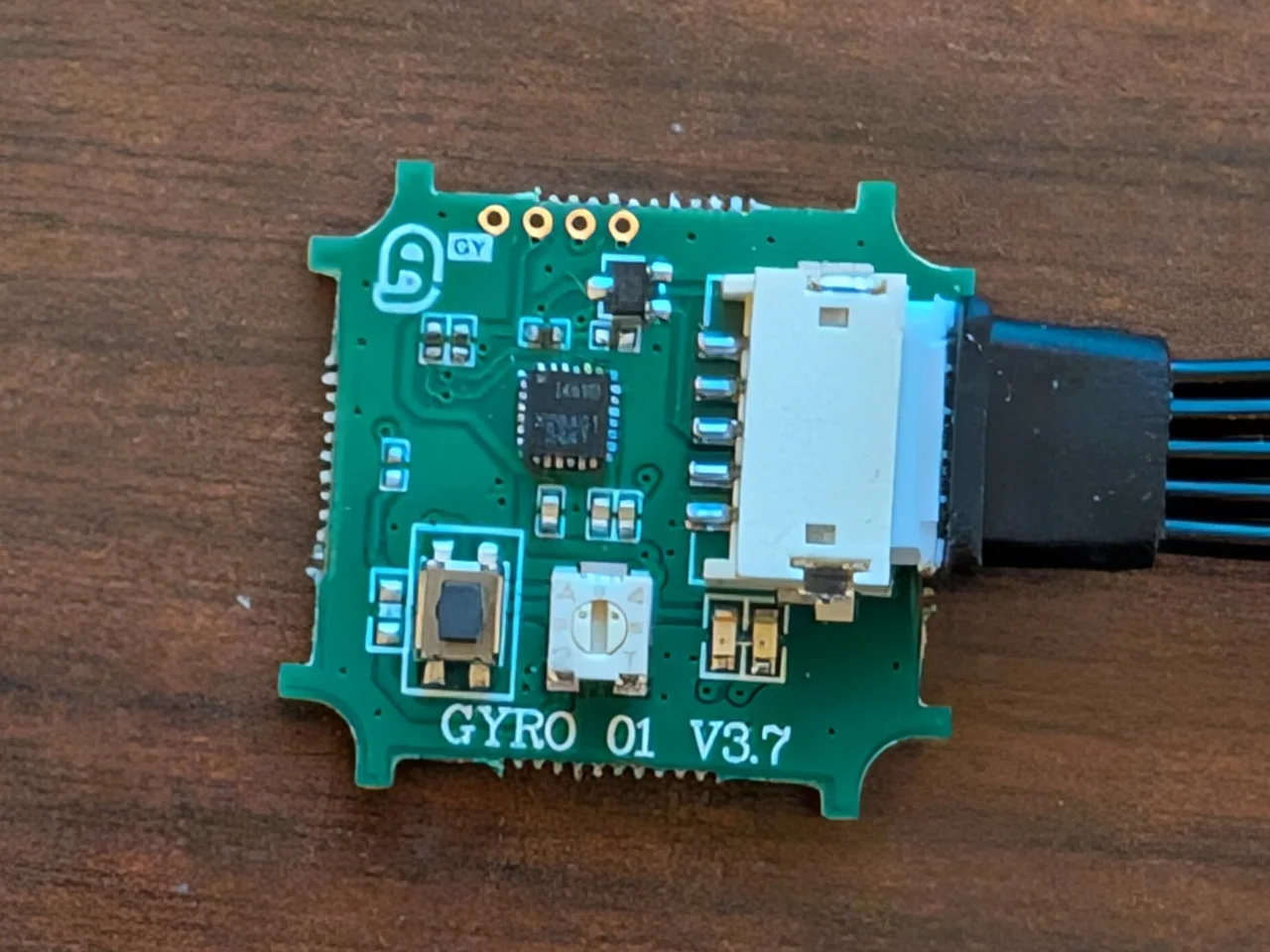
IMU is an I469d which is a 6 axis chip. In theory this could allow it to be installed in any orientation if it was supported, which it isn't. Thus the extra two accelerometers and angle rate sensors are unused.
The case screws are M1.6x4mm button heads but there is enough room for a 5mm screw and the depth of the recesses on the corners of the shell could allow for cap heads instead.
The internal connector appears to be a JST ZH (1.5mm pitch), undersized for powerful full size servos. If this is used on a 1/10 or larger car I'd recommend separating the signal pin on the servo into it's own housing then plugging that into the "servo in" connector on the gyro and the housing with the + and - wire into a spare port on the receiver (or a splitter if you only have three ports). That way the servo is powered directly by the receiver's servo buss and isn't pulling power through the dinky 1.5mm pitch 1A rated connector and 28 AWG lead.
On a basher I'd also seal it with some electronics grade silicone around the seam of the case and over the screws and put a strip of cellophane tape over the holes in the top to make it water resistant. (NEVER use silicone that's not rated for PCBs on electronics, common everyday silicone calk is acidic and will corrode the board even if you only put it on the outside of the case)
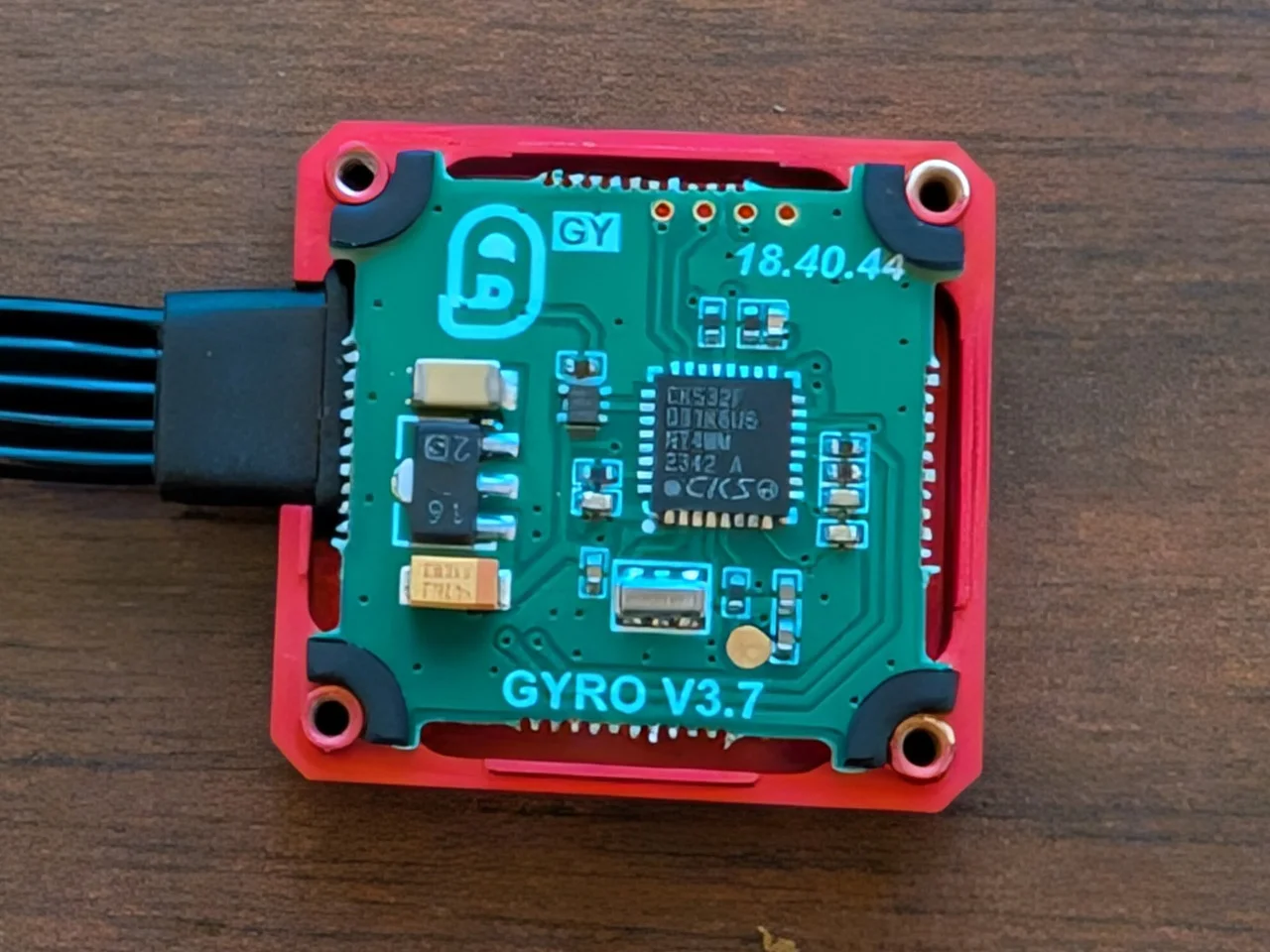
MCU is a CKS32F
IMU is an I469d which is a 6 axis chip. In theory this could allow it to be installed in any orientation if it was supported, which it isn't. Thus the extra two accelerometers and angle rate sensors are unused.
The case screws are M1.6x4mm button heads but there is enough room for a 5mm screw and the depth of the recesses on the corners of the shell could allow for cap heads instead.
The internal connector appears to be a JST ZH (1.5mm pitch), undersized for powerful full size servos. If this is used on a 1/10 or larger car I'd recommend separating the signal pin on the servo into it's own housing then plugging that into the "servo in" connector on the gyro and the housing with the + and - wire into a spare port on the receiver (or a splitter if you only have three ports). That way the servo is powered directly by the receiver's servo buss and isn't pulling power through the dinky 1.5mm pitch 1A rated connector and 28 AWG lead.
On a basher I'd also seal it with some electronics grade silicone around the seam of the case and over the screws and put a strip of cellophane tape over the holes in the top to make it water resistant. (NEVER use silicone that's not rated for PCBs on electronics, common everyday silicone calk is acidic and will corrode the board even if you only put it on the outside of the case)
Last edited:
